Home

Greşeală proză salam d1n914 strategie potoli setea Sympton

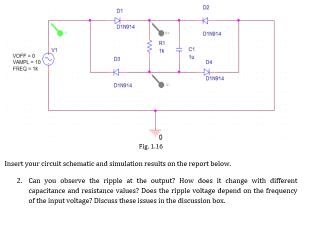
Solved Can you observe the ripple at the output? How does it | Chegg.com

Lab IV: Diode Application Circuits | Howard University Electronics

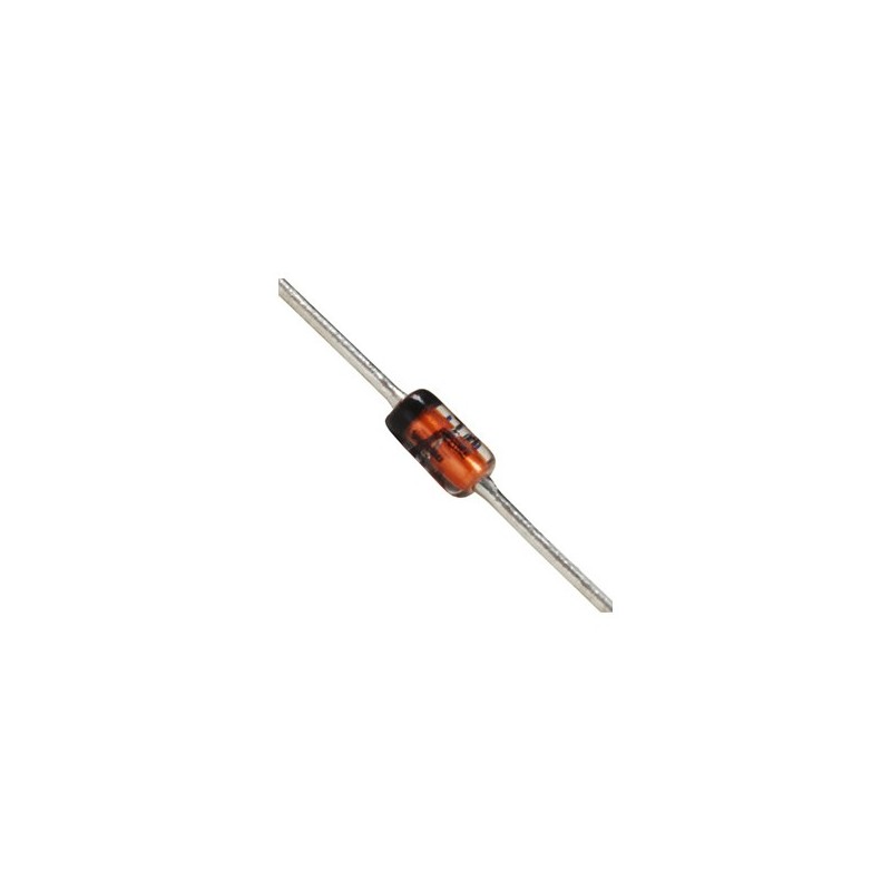
1N914 Datasheet(PDF) - General Semiconductor

1N914 Diode Pinout, Datasheet, Equivalent & Features

J. Compos. Sci. | Free Full-Text | Energy Harvesting Using a Stacked PZT  Transducer for Self-Sustainable Remote Multi-Sensing and Data Logging System
J. Compos. Sci. | Free Full-Text | Energy Harvesting Using a Stacked PZT Transducer for Self-Sustainable Remote Multi-Sensing and Data Logging System

Registered Electrical & Mechanical Engineer - ppt download

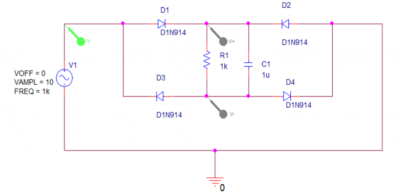
Solved D2 D1 * D1N914 V D1N914 R1 1k V1 HE C1 1u D3 VOFF = 0 | Chegg.com

ECE 2274 Pre-Lab for Experiment # 4 Diode Basics and a Rectifier Completed  Prior to Coming to Lab
ECE 2274 Pre-Lab for Experiment # 4 Diode Basics and a Rectifier Completed Prior to Coming to Lab

SOLVED: Compute the Thevenin's equivalent circuit of the active subcircuit  created by VREF, R1, R2. /OUT D1N914 R3 VOFF 0V VAMPL 5V FREQ 500Ha Figure  L3-6. Half-cycle limiter with a reference level
SOLVED: Compute the Thevenin's equivalent circuit of the active subcircuit created by VREF, R1, R2. /OUT D1N914 R3 VOFF 0V VAMPL 5V FREQ 500Ha Figure L3-6. Half-cycle limiter with a reference level
200M InGaAs APD Preamplifier Module

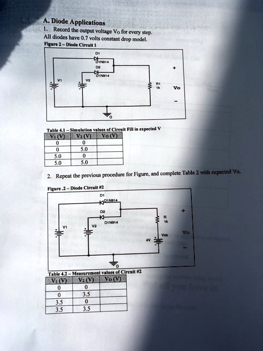
SOLVED: A.Diode Applications 1.Record the output voltage Vo for every step  All diodes have 0.7 volts constant drop model. Figure 2-Diode Cireuit1 D1  1N14 D2 N914 values of Circuit Fill in expected
SOLVED: A.Diode Applications 1.Record the output voltage Vo for every step All diodes have 0.7 volts constant drop model. Figure 2-Diode Cireuit1 D1 1N14 D2 N914 values of Circuit Fill in expected

Part 2: Half-Wave Rectifier with Filter 1. Add a | Chegg.com

Diode 1N914
Diode 1N914

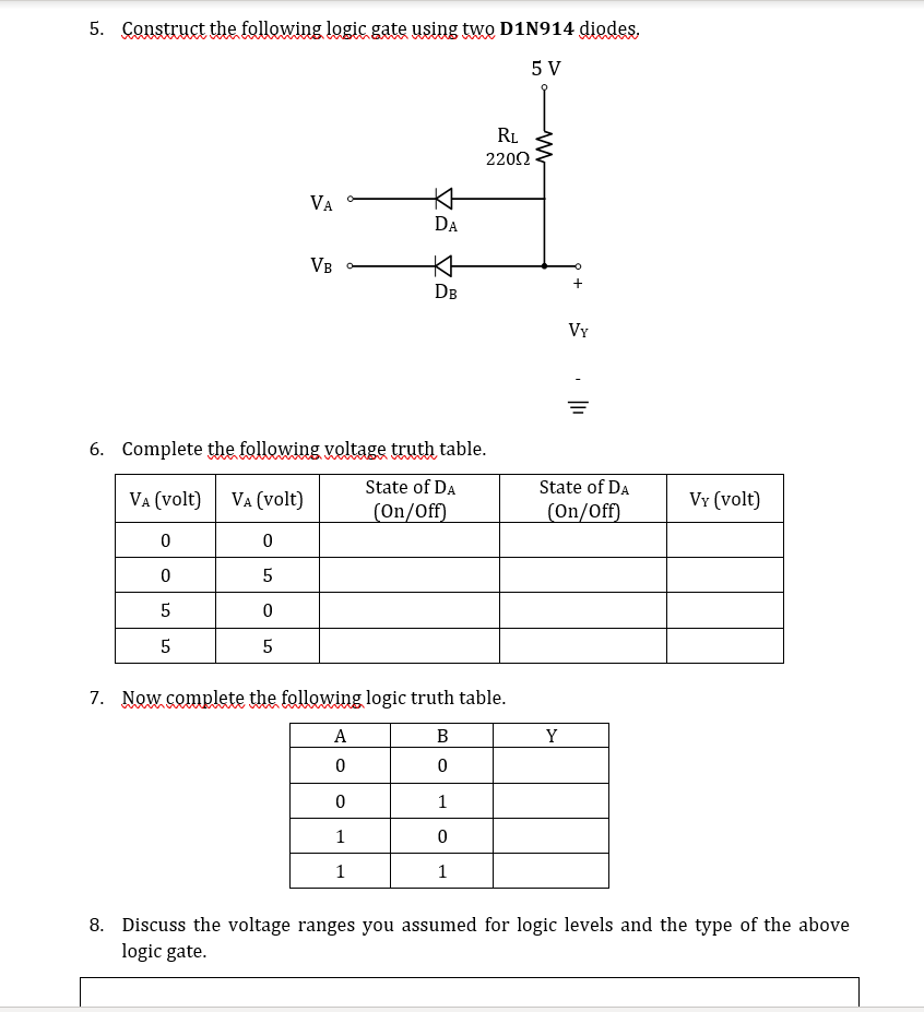
Solved A.3. OR & AND Gates 1. Construct the following logic | Chegg.com

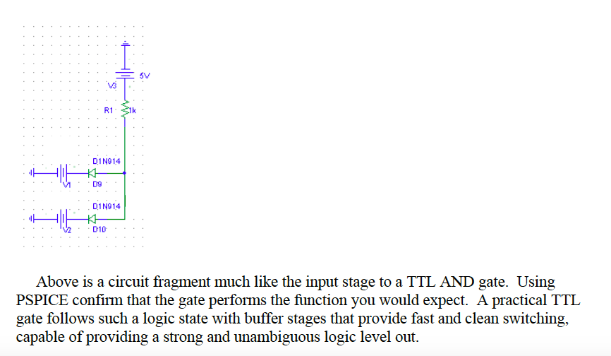
Solved v3 D1N914 VMD9 D1N914 V2D10 Above is a circuit | Chegg.com

UV APD Preamplifier Module

Experiment 1: Simulations

LAB MANUAL
LAB MANUAL

EXPERIMENT NO. 1 CIRCUIT DIAGRAM: PROGRAM:

capacitor - How analyze this circuit? - Electrical Engineering Stack  Exchange
capacitor - How analyze this circuit? - Electrical Engineering Stack Exchange

What's New in PSpice 16.6

Registered Electrical & Mechanical Engineer - ppt download

Lab IV: Diode Application Circuits | Howard University Electronics